Board Bring-up: Savageboard
Savageboard is i.MX6 based board which supports LVDS, HDMI, ethernet, eMMC, SD card and etc.
Main reason of choosing this board is testing Etnaviv user-space driver for Wayland.
![]()
Board manufacturer - Poslab supports the BSP but it's not mainline u-boot and kernel.
So I decided to bring-up system based on mainline.
Let's look inside the components in the board.
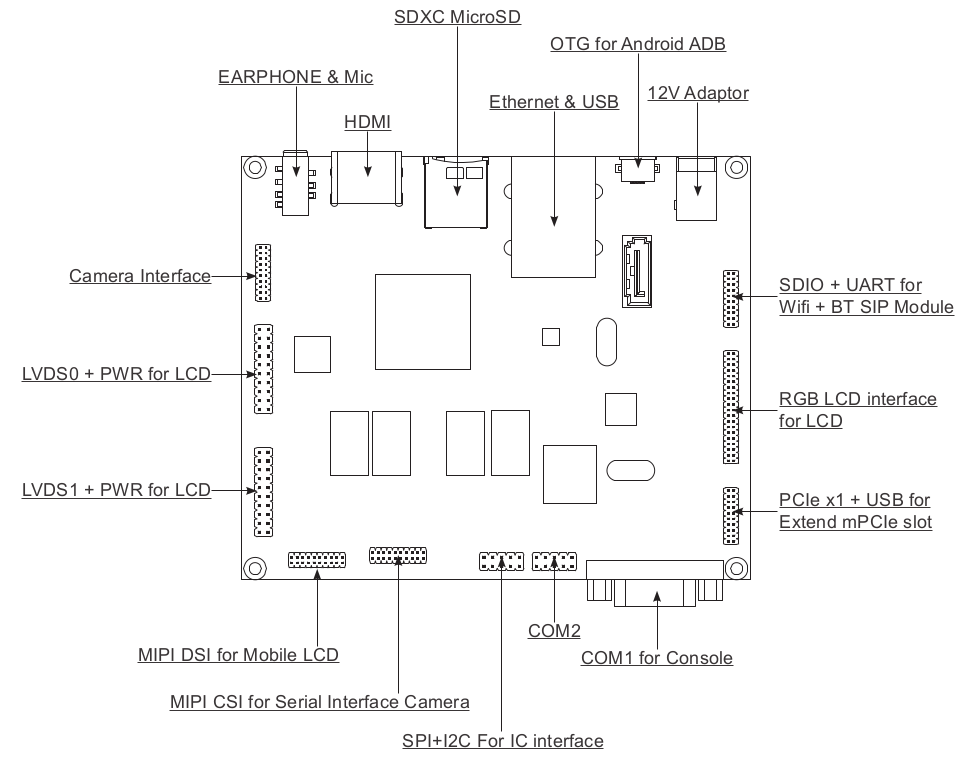
Device tree structure
Savageboard is i.MX6 based board, so internal dtsi file (imx6q.dtsi or imx6dl.dtsi) is reused. The board dtsi file will describe each HW component. The only difference between Savageboard Quad and Dual is SATA interface support.

COM1 for debug console
First of all, we need to set-up the UART for the debugging purpose.

Two pins of i.MX6 are used for UART communication in this board. ADM3232E is the transceiver which transmit TTL/CMOS signal to RS232. CSI0DATA10 and CSI0DATA11 should be configured as UART pin usage. According to the datasheet, CSI0DATA10 has multiple pinmux modes.
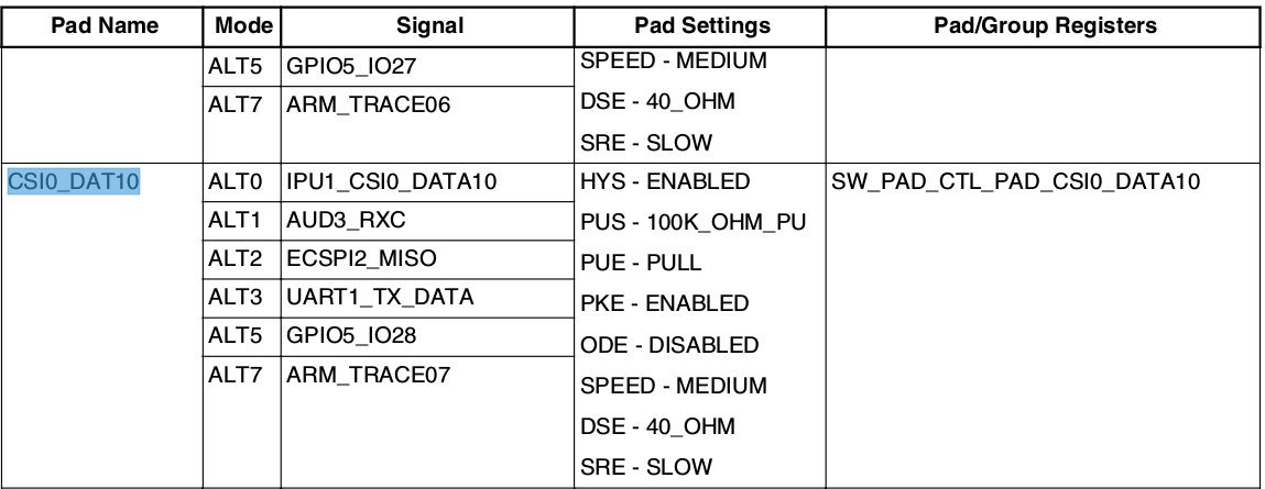
ALT3 mode is for UART1 TX. To configure this mode, SW_PAD_CTL_PAD_CSI0_DATA10 register should be updated.
The address of this register is 20E_0650h (= 20E_0000h base + 650h offset)
The value will be 0x1b0b1 which means hysterisis enabled, 100k ohm pull up on the pad, pull up, CMOS ouput, medium speed, fast slew rate. For the details, please refer to page 2502 in the i.MX6 Quad datasheet.

In the mainline kernel, i.MX6 pinctrl DT uses internal header named 'imx6q-pinfunc.h' or 'imx6dl-pinfunc.h' under arch/arm/dts/.
The structure of pin configuration is a type of tuple belows.
mux register | config register | input register | mux value | input value | pin config val
For example, CSI0_DAT10 and DAT11 for UART1 Tx/Rx are defined as
#define MX6QDL_PAD_CSI0_DAT10__UART1_TX_DATA        0x280 0x650 0x000 0x3 0x0
#define MX6QDL_PAD_CSI0_DAT11__UART1_RX_DATA        0x284 0x654 0x920 0x3 0x1
The definition has 5 tuples, additional item is the value of pad conf register. In this case, it is 0x1b0b1.

Here is the DT for UART1 debug console.
[arch/arm/dts/boot/imx6qdl-savageboard.dtsi]

/ {
       chosen {
               stdout-path = &uart1;
       };
};

&uart1 {
       pinctrl-names = "default";
       pinctrl-0 = <&pinctrl_uart1>;
       status = "okay";
};

&iomuxc {
       pinctrl_uart1: uart1grp {
               fsl,pins = <
                       MX6QDL_PAD_CSI0_DAT10__UART1_TX_DATA    0x1b0b1
                       MX6QDL_PAD_CSI0_DAT11__UART1_RX_DATA    0x1b0b1
               >;
       };
};
In arch/arm/boot/dts/imx6qdl.dtsi, uart1 and iomuxc are defined. So Savageboard just includes those DT properties and configures the pin pads.
Memory block
The DT property for memblock is optional because the u-boot already passed the information during the boot.
Anyway, no problem to add the memblock in the DT belows. Please note that the start address of DDR3 controller is 0x10000000 and the size is 1GB.
[arch/arm/dts/boot/imx6qdl-savageboard.dtsi]

/ {
...

    memory@10000000 {
        device_type = "memory";
        reg = <0x10000000 0x40000000>;
    };

...
};
HDMI
Let's look at the schematics of HDMI first.
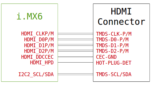
According to the i.MX6 datasheet, all HDMI pins are dedicated except I2C2 pins for EDID.
HDMI CEC implementation is optional but the wiring is mandatory. HPD pin is also dedicated pin. No pin mux is available.
The next step is checking the DT properties of i.MX6 HDMI driver. We can get the compatible string from imx6q.dtsi, it's "fsl,imx6q-hdmi".
[arch/arm/dts/boot/imx6q.dtsi]

&hdmi {
    compatible = "fsl,imx6q-hdmi";
};
OK, let's check the DT bindings.
[Documentation/devicetree/bindings/display/imx/hdmi.txt]

Optional properties:
 - ddc-i2c-bus: phandle of an I2C controller used for DDC EDID probing
Aha! So the I2C2 needs to be added here. Additionally, the pin configuration is required.
[arch/arm/dts/boot/imx6qdl-savageboard.dtsi]

&hdmi {
    ddc-i2c-bus = <&i2c2>;
    status = "okay";
};

&i2c2 {
    clock-frequency = <100000>;
    pinctrl-names = "default";
    pinctrl-0 = <&pinctrl_i2c2>;
    status = "okay";
};

&iomuxc {
    pinctrl_i2c2: i2c2grp {
        fsl,pins = <
            MX6QDL_PAD_KEY_COL3__I2C2_SCL           0x4001b8b1
            MX6QDL_PAD_KEY_ROW3__I2C2_SDA           0x4001b8b1
        >;
    };
};
The 'hdmi' and 'i2c2' properties are disabled by default, so enable them by adding status = "okay".
The pinmux structure is exactly same as UART, 0x4001b8b1 is for I2C pin configuration.
Done!
LCD Panel (LVDS)
To output display data to the LCD panel, LVDS interface and PWM controller are used. Here is the block diagram.
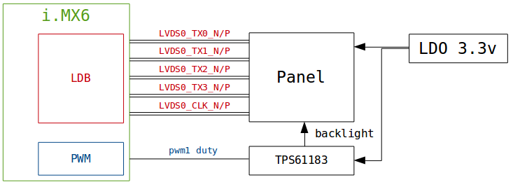
- LVDS display output to panel input
We should follow the graph DT bindings for the display. LDB is a LVDS controller in i.MX6 SoC. This driver has specific DT properties. For single channel, port4 should be defined in the device tree. (Documentation/devicetree/bindings/display/imx/ldb.txt). LVDS0 pinouts are dedicated pins. In other words, pinmux is not required.
[arch/arm/dts/boot/imx6qdl-savageboard.dtsi]

&ldb {
        status = "okay";

        lvds-channel@0 {
                reg = <0>;
                status = "okay";

                port@4 {
                        reg = <4>;

                        lvds0_out: endpoint {
                                remote-endpoint = <&panel_in>;
                        };
                };
        };
};
So, how to describe the panel input? AVIC TM097TDH02 panel is compatible with Hannstar HSD100PXN1 which is supported by 'panel-simple.c' under drivers/gpu/drm/panel. So we can just reuse it.
[arch/arm/dts/boot/imx6qdl-savageboard.dtsi]
/ {
...
panel {
compatible = "avic,tm097tdh02", "hannstar,hsd100pxn1";
backlight = <&panel_bl>;
power-supply = <®_3p3v>;
port {
panel_in: endpoint {
remote-endpoint = <&lvds0_out>;
};
};
};
...
};
Please note that remote-endpoints (lvds0_out and panel_in) are linked each other.
Additionally, panel-simple driver is the PWM consumer for the backlight control. PWM1 is used in this board.
- Backlight
We can use Linux generic PWM backlight driver. Please refer to the bindings. (Documentation/devicetree/bindings/leds/backlight/pwm-backlight.txt)
[arch/arm/dts/boot/imx6qdl-savageboard.dtsi]
/ {
panel_bl: backlight {
compatible = "pwm-backlight";
brightness-levels = <0 4 8 16 32 64 128 255>;
default-brightness-level = <4>;
power-supply = <®_3p3v>;
pwms = <&pwm1 0 10000>;
};
};
- PWM controller
To enable PWM 1 controller, it's very simple - pinmux for SD1_DAT3.
[arch/arm/dts/boot/imx6qdl-savageboard.dtsi]

&pwm1 {
        pinctrl-names = "default";
        pinctrl-0 = <&pinctrl_pwm1>;
        status = "okay";
};

&iomuxc {
        pinctrl_pwm1: pwm1grp {
                fsl,pins = <
                        MX6QDL_PAD_SD1_DAT3__PWM1_OUT           0x1b0b1
                >;
        };
};
Done!
Ethernet
Power button
GPIO power button is useful to test suspend/resume case. A switch on/off event is detectable from EIM_DA7 in i.MX6.
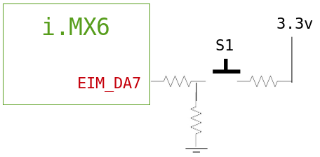
The EIM_DA7 pin can be configured as GPIO3_7 with ALT5 mux mode. To handle the switch on/off event, this pin should be GPIO input and active low detectable. So generic GPIO power button DT properties are added as belows.
[arch/arm/boot/dts/imx6qdl-savageboard.dtsi]

/ {
...
        gpio-keys {
                compatible = "gpio-keys";
                pinctrl-names = "default";
                pinctrl-0 = <&pinctrl_gpio_keys>;

                power {
                        gpios = <&gpio3 7 GPIO_ACTIVE_LOW>;
                        label = "Power Button";
                        linux,code = <KEY_POWER>;
                        wakeup-source;
                };
        };
...
};

&iomuxc {
        pinctrl_gpio_keys: gpiokeysgrp {
                fsl,pins = <
                        MX6QDL_PAD_EIM_DA7__GPIO3_IO07          0x1b0b1
                >;
        };
};
Please note that 'wakup-source' is required to resume the system from the suspend mode.